







1. Introduction for Installation Qualification Qualification Protocol cum Report for Nitrogen Gas Generation & Distribution System:
The Installation Qualification (IQ) Protocol Cum Report for the Nitrogen Gas Generation and Distribution System is prepared to provide documented evidence that the nitrogen generation system, its components, utilities, piping, instruments, and associated accessories are installed correctly and in accordance with the approved design specifications and supplier requirements. The system is installed in the Utility Block and has a rated capacity of 10 Nm³/hr. The main purpose of the IQ activity is to confirm that the installation is suitable before proceeding with further qualification and routine operation. The nitrogen generation system works on Pressure Swing Adsorption (PSA) technology. Atmospheric compressed air passes through specially designed adsorption beds containing activated alumina and Carbon Molecular Sieves (CMS). These materials remove moisture, oxygen, and carbon dioxide from compressed air, allowing nitrogen of approximately 99.5% purity to be produced. The specified outlet pressure is 5.5 kg/cm², and the system is designed for a dew point of approximately –40°C. The generated nitrogen is collected through a surge vessel and subsequently supplied to the required user points. An oxygen analyzer continuously checks oxygen impurity in the generated nitrogen. When nitrogen purity is outside the required limit, an interlocked three-way vent valve diverts the gas to atmosphere until the desired purity is achieved. During Installation Qualification, important aspects such as equipment location, leveling, mechanical and electrical installation, piping, component assembly, material of construction, pressure vessels, filters, nitrogen receiver, oxygen analyzer, and supporting documentation are verified. Required documents such as approved Design Qualification, instrumentation diagrams, technical specifications, calibration certificates, and material certificates are also checked for completeness and approval. Successful completion of the IQ provides assurance that the nitrogen generation and distribution system has been properly installed and is ready for the next stage of qualification.
Skip to PDF content2. Flow Diagram for Installation Qualification Qualification Protocol cum Report for Nitrogen Gas Generation & Distribution System:
The flow diagram describes the complete working sequence of the Nitrogen Gas Generation and Distribution System. Compressed atmospheric air first enters the system and passes through filtration and drying stages to remove dust, oil, and moisture. The treated air then enters the PSA nitrogen generator, where activated alumina and Carbon Molecular Sieves selectively remove moisture, oxygen, and carbon dioxide. As a result, nitrogen of approximately 99.5% purity is produced.
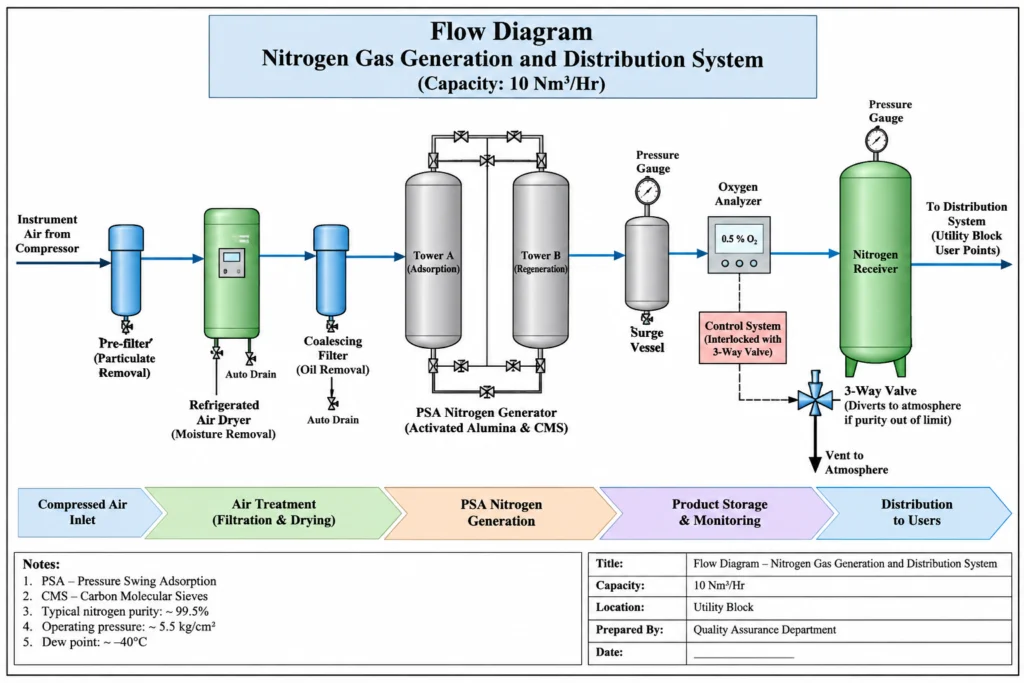
The generated nitrogen is collected in a surge vessel and then monitored using an oxygen analyzer. If the oxygen content is higher than the specified limit, an interlocked three-way valve vents the impure nitrogen to atmosphere until acceptable purity is achieved. Once the required quality is achieved, nitrogen is stored in the receiver and distributed to the required user points. The system operates at a capacity of 10 Nm³/hr with an outlet pressure of 5.5 kg/cm².
3. Brainstorming Analysis for Installation Qualification Protocol Cum Report for the Nitrogen Gas Generation and Distribution System was not performed:
The brainstorming diagram explains the possible reasons why the Installation Qualification Protocol Cum Report for the Nitrogen Gas Generation and Distribution System was not performed. The main problem is shown at the center, while different possible causes are written on sticky notes around it. These causes include protocol not prepared, QA approval pending, engineering coordination missing, production support not available, installation checks not scheduled, and required documents not available. Other possible reasons include missing Design Qualification references, unavailable calibration and MOC certificates, incomplete vendor documents, shortage of manpower, lack of training, unclear responsibilities, poor planning, weak management follow-up, and communication gaps between departments. The diagram also highlights pending utility block readiness and lack of proper review of equipment details.
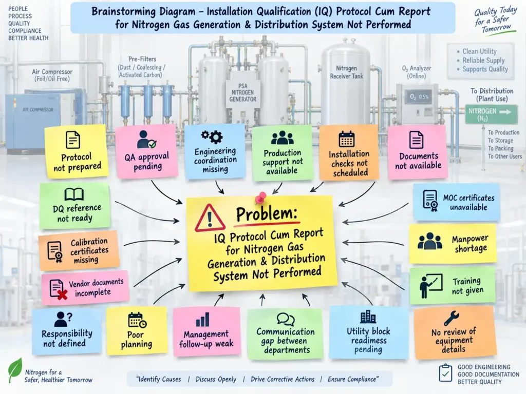
This brainstorming exercise helps the team discuss all possible causes openly, identify the most important gaps, assign responsibilities, and plan corrective actions so that the Installation Qualification activity can be completed properly and on time.
4. 5 Why Analysis for Installation Qualification (IQ) Protocol Cum Report for the Nitrogen Gas Generation and Distribution System was not performed:
The 5 Why Analysis was used to identify the root cause for why the Installation Qualification (IQ) Protocol Cum Report for the Nitrogen Gas Generation and Distribution System was not performed. The analysis starts with the main problem and asks “Why?” repeatedly. First, the IQ activity was not performed because it was not properly scheduled and executed after installation. The next reason identified was that required documents, checklists, and installation readiness were incomplete. Further analysis showed that coordination among Quality Assurance, Engineering, and Production was not completed on time.
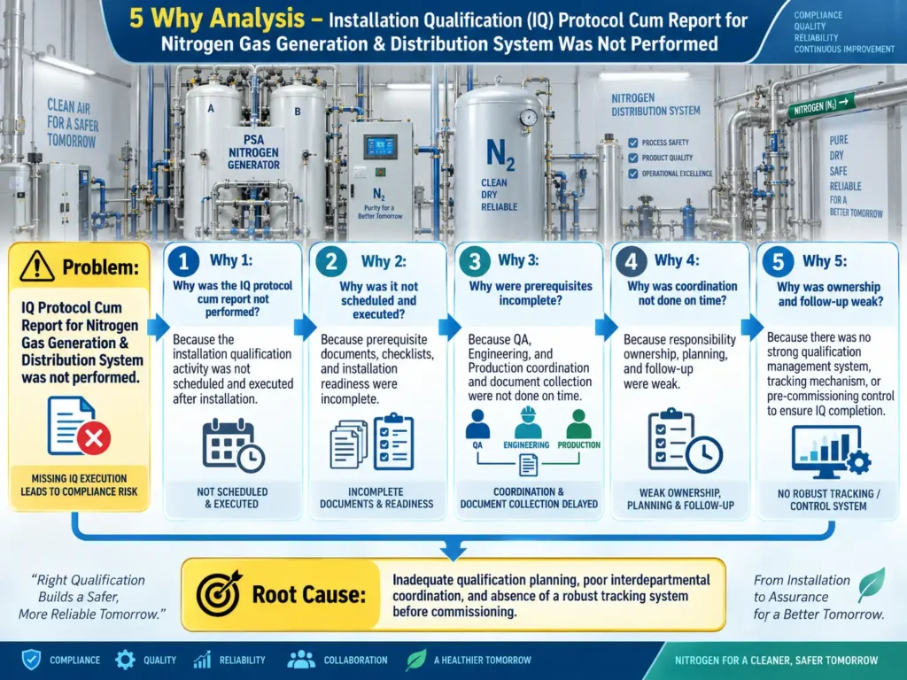
The investigation then found that responsibility, ownership, planning, and follow-up were weak. Finally, the deepest cause was identified as the absence of a strong qualification management and tracking system to ensure completion of IQ before commissioning. Therefore, the root cause is inadequate qualification planning, poor interdepartmental coordination, unclear ownership, and insufficient monitoring of qualification activities.
5. Heat Map Analysis for Installation Qualification (IQ) Protocol Cum Report for the Nitrogen Gas Generation and Distribution System was not performed:
The Heat Map Analysis shows the risk level created when the Installation Qualification (IQ) Protocol Cum Report for the Nitrogen Gas Generation and Distribution System was not performed. The diagram evaluates each possible cause based on severity and likelihood. Risks are grouped from low to critical so that the most important issues can be handled first. The highest risks include protocol not prepared, installation checks not scheduled, missing documentation, incomplete vendor records, weak engineering coordination, poor communication, manpower shortage, and unavailable MOC certificates. Medium risks include pending QA approval, missing calibration certificates, poor planning, and weak management follow-up. Low-risk factors include unclear responsibility, lack of production support, and incomplete training.
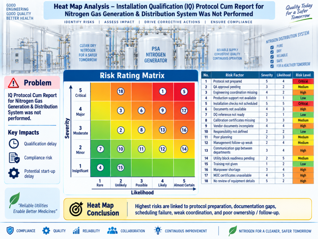
The heat map helps the team quickly understand which gaps may cause serious qualification, compliance, or start-up delays. It also supports prioritization of corrective actions, better planning, stronger departmental coordination, and timely completion of the Installation Qualification activity.
6. Fault Tree Analysis for Installation Qualification (IQ) Protocol Cum Report for the Nitrogen Gas Generation and Distribution System not performed:
The Fault Tree Analysis (FTA) explains the possible causes behind the failure to perform the Installation Qualification (IQ) Protocol Cum Report for the Nitrogen Gas Generation and Distribution System. The main problem is placed at the top, and the contributing causes are divided into major categories. The important causes include documentation failure, poor planning and scheduling, weak coordination between departments, shortage of resources and training, and inadequate management control. Documentation-related issues may include an unprepared protocol, missing DQ references, calibration certificates, and incomplete MOC or vendor documents. Planning problems may include unscheduled installation checks and incomplete utility readiness. Coordination gaps between QA, Engineering, and Production can further delay the activity.
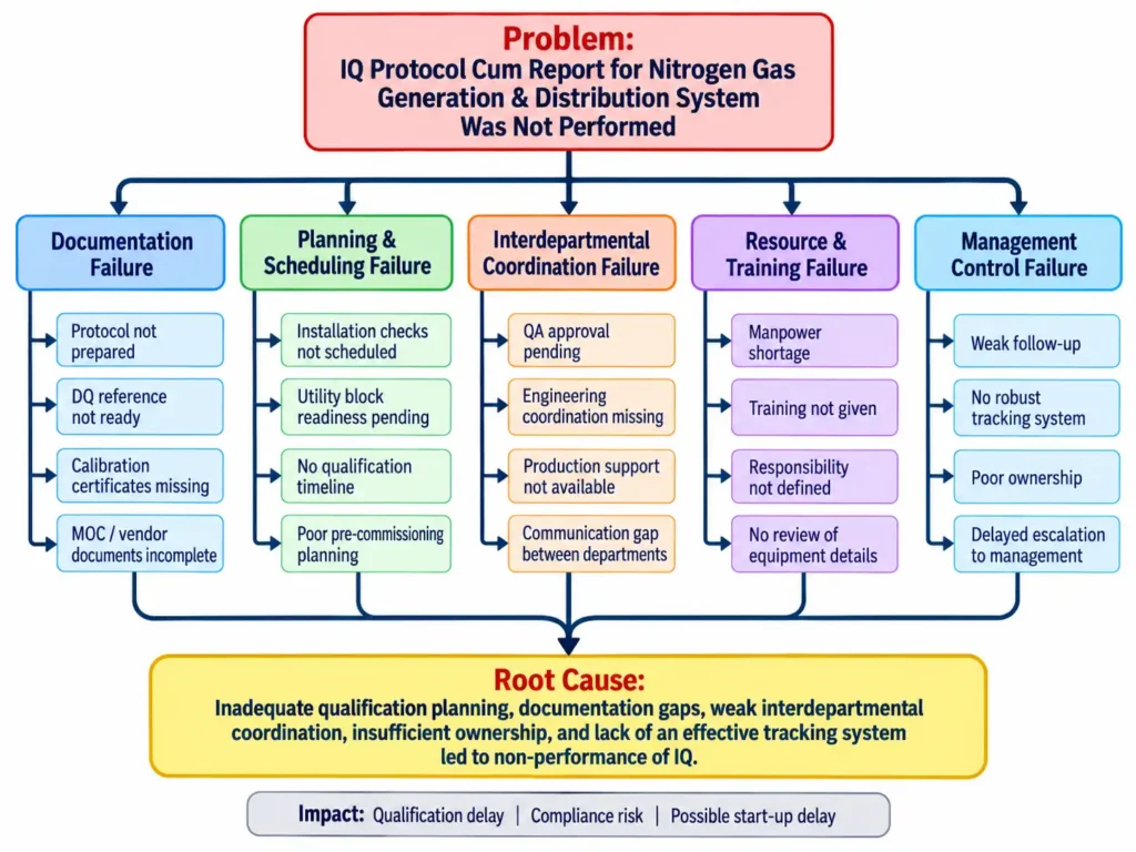
The analysis indicates that the probable root cause is inadequate qualification planning, documentation gaps, weak departmental coordination, poor ownership, and lack of an effective tracking system, which can result in qualification delays and compliance risks.
7. Pareto Analysis for Installation Qualification (IQ) Protocol Cum Report for the Nitrogen Gas Generation and Distribution System not performed:
The Pareto Analysis helps identify the most important causes responsible for the Installation Qualification (IQ) Protocol Cum Report for the Nitrogen Gas Generation and Distribution System not being performed. The chart arranges the causes from highest to lowest contribution so the team can focus first on the issues creating the greatest impact. The major contributors are installation checks not scheduled, protocol not prepared, required documents not available, weak engineering coordination, and incomplete vendor or MOC documentation. Other contributing factors include poor planning, communication gaps between departments, manpower shortage, pending QA approval, missing calibration certificates, lack of training, and unclear responsibilities.
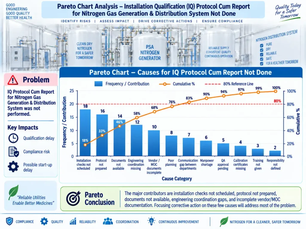
The cumulative percentage line shows that a small number of key causes contribute to most of the overall problem. Therefore, priority should be given to improving qualification planning, preparing and approving the protocol on time, ensuring document readiness, strengthening coordination between QA, Engineering, and Production, and establishing proper tracking and follow-up.
8. Questions & Answers – Installation Qualification of Nitrogen Gas Generation & Distribution System:
- Q: What is the purpose of the Installation Qualification Protocol Cum Report?
A: Its purpose is to provide documented evidence that the Nitrogen Gas Generation and Distribution System and its components are installed according to approved design specifications and supplier requirements. - Q: Where is the nitrogen generation system installed?
A: The system is installed in the Utility Block. - Q: What is the capacity of the nitrogen generation system?
A: The specified capacity is 10 Nm³/hr. - Q: Which technology is used for nitrogen generation?
A: The system uses Pressure Swing Adsorption (PSA) technology. - Q: What nitrogen purity is specified in the protocol?
A: The specified nitrogen purity is approximately 99.5%. - Q: What are the specified outlet pressure and dew point?
A: The outlet pressure is 5.5 kg/cm², and the specified dew point is approximately –40°C. - Q: What is the function of Carbon Molecular Sieves in the PSA system?
A: CMS assists in selectively removing oxygen and carbon dioxide from compressed air so that nitrogen can be generated. - Q: What is the purpose of the surge vessel?
A: The surge vessel collects generated nitrogen from the PSA system before it is transferred toward storage or user points. - Q: What is the function of the oxygen analyzer?
A: It measures oxygen impurity in the generated nitrogen and helps confirm that the required nitrogen purity is achieved. - Q: What happens when the nitrogen purity is outside the required limit?
A: The interlocked three-way valve vents the nitrogen to atmosphere until the required purity is restored. - Q: Which documents should be available before performing IQ?
A: Important documents include the approved Design Qualification, instrumentation diagram, equipment technical specifications, calibration certificates, and material-of-construction certificates. - Q: What installation checks are covered during IQ?
A: Checks include mechanical installation, physical condition, component assembly, electrical installation, pipeline installation, leakage protection, and piping conformity with approved drawings. - Q: Which departments are involved in Installation Qualification?
A: Quality Assurance, Production, and Engineering participate in review, execution, coordination, monitoring, technical support, and approval of the qualification activity. - Q: What should be done if the IQ activity was not performed?
A: The omission should be formally evaluated through the applicable deviation or quality-system process, its impact assessed, the reason investigated, and the IQ completed with approved documentation before relying on the system as qualified. The attached protocol itself provides sections for recording deviations, change control, follow-up review, conclusion, and recommendation. - Q: What is the expected outcome after successful Installation Qualification?
A: Successful IQ should demonstrate that the system, its components, piping, instruments, documentation, and installation conditions meet the predefined requirements, supporting progression to subsequent qualification activities.
9. Reference Guidelines for the Nitrogen Gas Generation and Distribution System:
- Master Validation Plan (MVP) – Site-approved validation framework governing qualification and validation activities.
- Schedule M – Good Manufacturing Practices and Requirements of Premises, Plant and Equipment for Pharmaceutical Products – Applicable Indian GMP requirements for pharmaceutical facilities, utilities, equipment installation, qualification, maintenance, and documentation.
- WHO – Quality Assurance of Pharmaceuticals, Volume 2: Good Manufacturing Practices and Inspection – Guidance covering GMP expectations for pharmaceutical premises, utilities, equipment, qualification, validation, documentation, and inspection practices.
- Approved Design Qualification (DQ) – The IQ should verify that the installed nitrogen system complies with approved design requirements, drawings, and supplier specifications. The protocol requires an executed and approved DQ before IQ execution.
- Approved Engineering Drawings and Instrumentation Diagrams – Used to confirm correct installation of piping, instruments, components, and system configuration.
- Manufacturer/Supplier Technical Documentation – Equipment specifications, component details, material certificates, operating data, and installation requirements should be verified during IQ.
- Calibration Certificates – Instruments used for pressure, oxygen monitoring, flow, and other critical measurements should have valid calibration documentation.