







OEL Sampling Plan and Rationale for Sampling Locations
The Operator Exposure Level (OEL) Sampling Plan is designed to evaluate potential airborne exposure around isolators and associated containment equipment during normal operation. The plan uses three main sampling types: Personal Breathing Zone (PBZ) sampling, background static sampling, and continuous static sampling, with a pre-trial background sample taken before each iteration. Sampling points are positioned near operator working zones, glove ports, doors, RTPs, sleeves, material-transfer interfaces, and other potential leakage points. The uploaded plan specifies the exact locations; the explanations below describe the likely containment-risk rationale for selecting each location.
1. Sampling Dispensing Isolator
The dispensing isolator uses one PBZ sample, six background static samples, one continuous static sample and a pre-trial background sample.
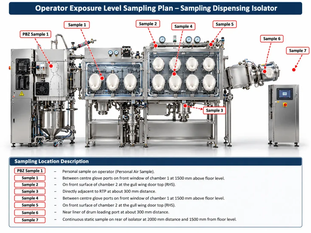
PBZ Sample 1 – Personal sample on operator
This sampler is positioned on the operator to estimate the airborne concentration in the operator’s breathing zone during dispensing activities. It represents the exposure most relevant to the person performing the operation and helps determine whether containment is adequate at the operator interface.
Sample 1 – Between centre glove ports on front window, Chamber 1, at 1500 mm height
This point is selected because glove ports are direct operator-interaction locations. Repeated glove movement, manipulation of material and potential leakage around glove-port seals can make this a critical containment location. The height also approximately represents the operator’s working/breathing level.
Sample 2 – Front surface of Chamber 2 at Gull Wing Door top, RHS
The Gull Wing Door is an opening and sealing interface. Door joints, gaskets and corners can be potential leakage paths if containment integrity is inadequate; therefore the upper door area is monitored as a worst-case boundary point.
Sample 3 – Adjacent to RTP at approximately 300 mm
The Rapid Transfer Port is used for transferring materials into or out of the isolator. Docking, undocking and opening operations can create a risk of powder escape, so a sampler is placed close to the RTP to detect any airborne release.
Sample 4 – Between centre glove ports on front window, Chamber 1, at 1500 mm height
This location again monitors the operator-interface zone around the glove ports. The selection is intended to detect any release occurring during manual manipulation inside the chamber and to represent a likely operator-exposure location.
Sample 5 – Front surface of Chamber 2 at Gull Wing Door top, RHS
This sampling location evaluates leakage around the second critical door/interface area. It is particularly important because movable doors and gasketed joints may present greater containment risk than fixed surfaces.
Sample 6 – Near liner of drum loading port at approximately 300 mm
The drum loading port is a major material-transfer point. Connecting, disconnecting or manipulating liners may generate dust or cause powder escape; therefore sampling close to this location provides a direct indication of containment performance during material charging.
Sample 7 – Continuous static sample at rear of isolator, 2000 mm distance and 1500 mm height
The continuous sampler is intended to provide an overall indication of airborne contamination throughout the test period. Positioning it away from immediate operator activity allows it to monitor general background contamination around the isolator.
Pre-Trial Sample – In front of isolator, 2000 mm distance and 1500 mm height
This sample establishes the background airborne level before the test starts. It helps distinguish contamination already present in the room from contamination generated during the isolator operation.
2. IPQC Isolator Sampling Plan
The IPQC isolator uses one PBZ sample, three background static samples, one continuous static sample and a pre-trial sample.
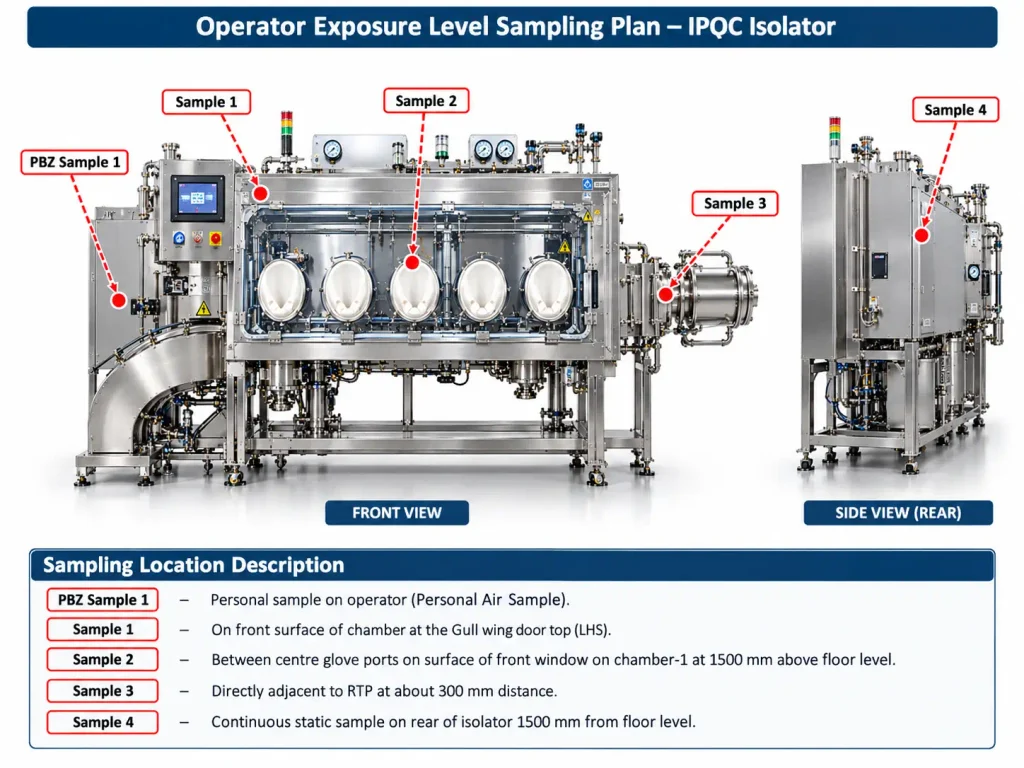
PBZ Sample 1 – Personal sample on operator
Selected to measure the operator’s direct potential inhalation exposure while performing IPQC activities.
Sample 1 – Gull Wing Door top, LHS
This monitors a potential leakage path around the door seal and opening mechanism, especially during opening, closing or manipulation.
Sample 2 – Between centre glove ports at 1500 mm height
This evaluates airborne contamination at the main operator-interaction point. Glove manipulation can stress glove-port seals and may cause release if the system is not fully contained.
Sample 3 – Adjacent to RTP at approximately 300 mm
The RTP is a material-transfer interface and therefore a higher-risk point for leakage during docking, undocking and transfer.
Sample 4 – Continuous static sample at rear of isolator, 1500 mm above floor
This monitors the general surrounding environment continuously during the operation and detects contamination that may migrate away from specific leakage points.
Pre-Trial Sample
Taken in front of the isolator at 2000 mm distance and 1500 mm height to establish baseline contamination before operation.
3. Sampling Table
For the sampling table, the plan identifies one PBZ sample, four background static samples and one continuous sample.
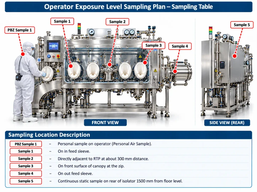
PBZ Sample 1 – Personal sample on operator
Used to assess the concentration actually present in the operator’s breathing zone while material is being handled.
Sample 1 – On in-feed sleeve
The in-feed sleeve is a material-entry interface. Sleeve connections may allow dust leakage during charging or transfer, so this is considered a critical containment boundary.
Sample 2 – Adjacent to RTP at approximately 300 mm
Chosen because the RTP is a high-risk transfer interface where powder release could occur during connection, opening or material movement.
Sample 3 – Front surface of canopy at the zip
The zip is a flexible closure and may represent a weaker containment boundary compared with a fixed rigid surface. Sampling here can identify leakage from the canopy enclosure.
Sample 4 – On out-feed sleeve
The out-feed sleeve is a discharge-transfer point where material exits the contained system. Handling or disconnecting the sleeve may release powder, making it an important monitoring location.
Sample 5 – Continuous static sample at rear of isolator, 1500 mm height
This provides continuous monitoring of the surrounding environment and identifies any general spread of airborne contamination away from the direct transfer points.
4. Tablet Press Isolator Sampling Plan
The tablet press isolator has the most extensive sampling arrangement, with one PBZ sample, ten background static samples and one continuous static sample.
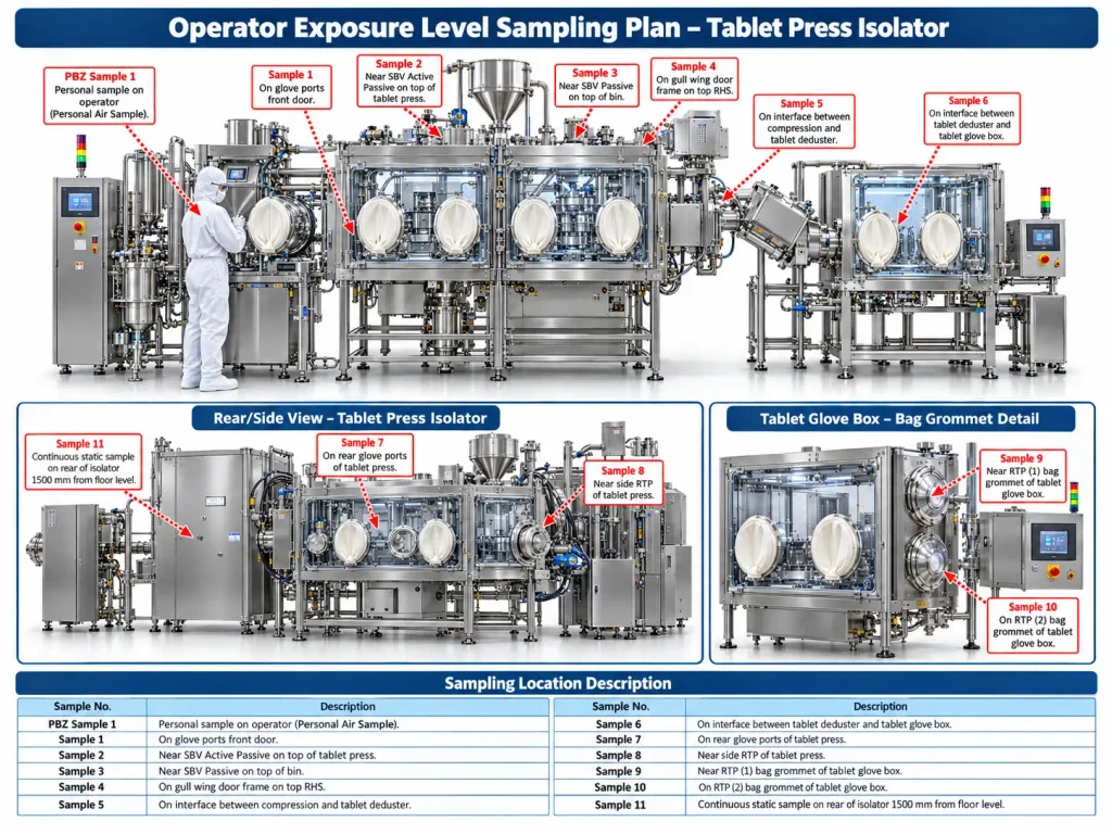
PBZ Sample 1 – Personal sample on operator
This directly evaluates operator inhalation exposure while operating, observing or interacting with the tablet press isolator.
Sample 1 – On glove ports front door
This location is selected because glove ports are frequent operator-interaction points. Repeated movement may challenge glove seals and create a potential leakage pathway.
Sample 2 – Near SBV Active/Passive on top of tablet press
The Split Butterfly Valve interface is a critical transfer connection. Docking and valve opening can create a powder-release risk if sealing is inadequate.
Sample 3 – Near SBV Passive on top of bin
This point monitors the second side of the material-transfer interface. It helps evaluate containment around the bin connection and passive valve during charging or discharge.
Sample 4 – Gull Wing Door frame, top RHS
Door frames and gasket interfaces can be potential leakage locations. This sample helps detect powder escaping through an imperfect door seal.
Sample 5 – Interface between compression machine and tablet deduster
This is a product-transfer interface where tablets and associated dust move from one machine to another. Mechanical connection points may permit dust escape and therefore represent a key worst-case location.
Sample 6 – Interface between tablet deduster and tablet glove box
This point monitors another downstream transfer connection. Dust remaining on tablets or generated during dedusting may potentially escape at the interface.
Sample 7 – Rear glove ports of tablet press
Rear glove ports may also be used for interventions, adjustment or cleaning. Sampling here verifies containment at another operator-access boundary.
Sample 8 – Near side RTP of tablet press
The side RTP is a transfer/opening point and may be used for waste or component transfer. Sampling close to it evaluates leakage associated with these transfer activities.
Sample 9 – Near RTP (1) bag grommet of tablet glove box
Bag-grommet interfaces are flexible connections used for material or waste handling. Manipulation and bag removal can release retained powder, so this represents a potentially high-risk point.
Sample 10 – On RTP (2) bag grommet of tablet glove box
This provides monitoring at the second bag-transfer interface to verify containment during bagging, waste removal or transfer operations.
Sample 11 – Continuous static sample at rear of isolator, 1500 mm height
This monitors overall airborne contamination around the isolator throughout the test period rather than focusing on one specific interface.
The plan also specifies a pre-trial sample before each iteration and three repetitions of PBZ, background static and continuous sampling.
5. Auto Coater Sampling Plan
The Auto Coater plan uses one PBZ sample, four background static samples, one continuous static sample and a pre-trial sample.
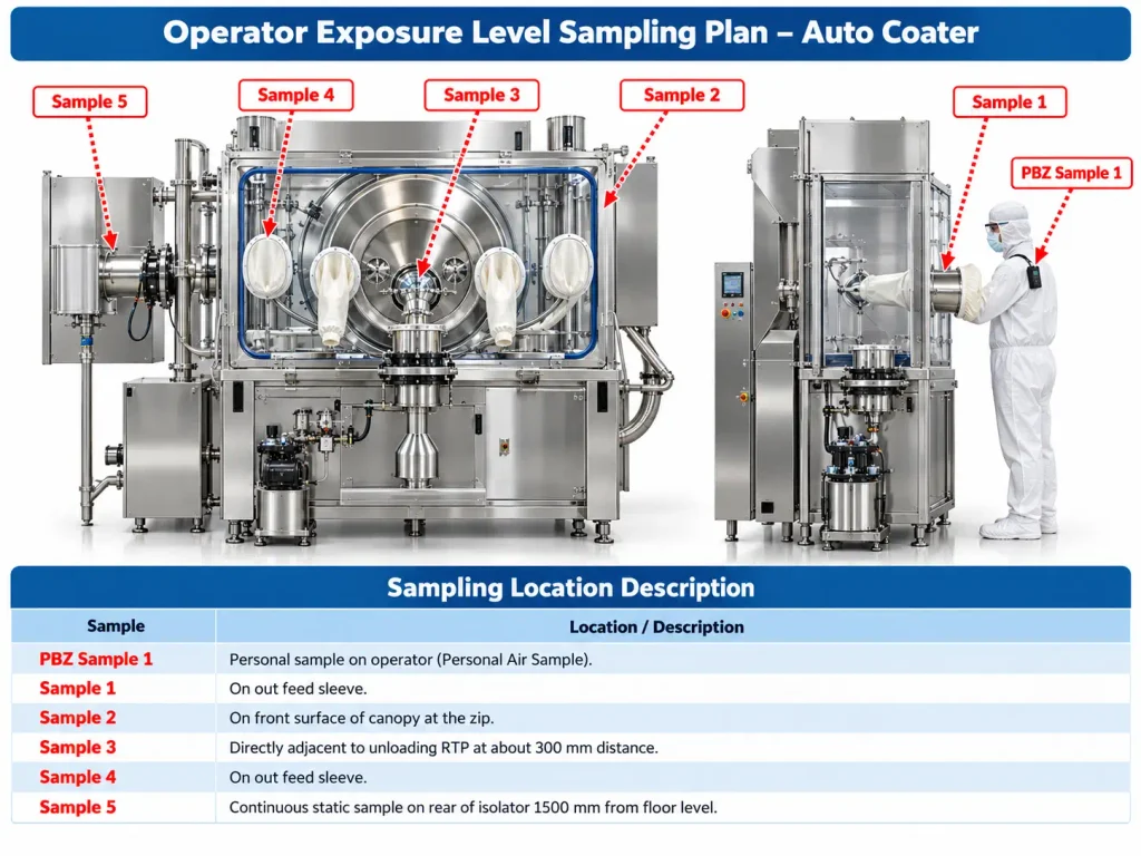
PBZ Sample 1 – Personal sample on operator
This is taken to evaluate the operator’s potential inhalation exposure during loading, coating-related handling or unloading activities.
Sample 1 – On out-feed sleeve
The out-feed sleeve is a product discharge point. Powder or residue may escape while transferring material or disconnecting the sleeve, making it a critical containment interface.
Sample 2 – Front surface of canopy at the zip
The canopy zip is a flexible closure and potential leakage boundary. Sampling here verifies that the enclosure remains contained during the operation.
Sample 3 – Adjacent to unloading RTP at approximately 300 mm
The unloading RTP is a major transfer point and can present a high risk of exposure during connection, product unloading and disconnection. Positioning the sampler nearby helps detect any release at this critical step.
Sample 4 – On out-feed sleeve
This location again targets the discharge pathway, where airborne contamination may occur as product exits the contained equipment.
Sample 5 – Continuous static sample at rear of isolator, 1500 mm height
This continuously monitors the general environment around the Auto Coater to detect contamination that spreads beyond the immediate discharge and transfer points.
Why these locations are generally selected
The common logic across the sampling plan is to monitor:
- Operator breathing zone → Actual personnel exposure.
- Glove ports → Frequent operator-intervention points.
- RTP/SBV interfaces → Material-transfer and docking points.
- Doors and gaskets → Possible containment-leakage boundaries.
- Sleeves and bag grommets → Flexible transfer/discharge connections.
- Equipment-to-equipment interfaces → Locations where dust may escape during product transfer.
- Continuous rear sample → General environmental contamination.
- Pre-trial sample → Baseline/background concentration before operation.
So, the sampling plan is essentially built around worst-case containment interfaces plus actual operator exposure locations.